


Energy Storage Converter (PCS)
Step-Up Transformer Cabin
Peak Shaving and Load Leveling
Grid Stability Enhancement
Emergency Backup Power Supply
Highly integrated design for ease of transportation and maintenance
Overview
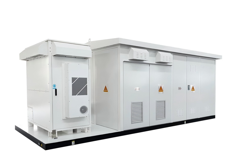
The integrated converter and booster cabin serves as the power unit of the energy storage system. As a vital component in modern energy conversion and transmission, its meticulous design and rational configuration are essential for efficient and stable operation.
This compact cabin seamlessly integrates two key functions: PCS and booster transmission. By storing and releasing electrical energy on demand, it balances the supply and demand of the power system, enhancing its stability and reliability. Furthermore, it achieves precise power balancing, improves overall sustainability, and reduces the peak-to-valley difference, providing crucial support for the operation and development of the entire power network.
Structural Features
Structural Features
2、Step-up transformer
3、High-voltage RMU
4、Low-voltage distribution cabinet and other equipment
Performance Advantages
Mounted on a robust skid base, this AC/DC conversion unit acts as the primary interface for battery charge and discharge control. Comprising a bidirectional DC/AC converter, advanced control logic, and filter circuits, it executes operational commands to manage DC-side battery flows while precisely regulating active and reactive power on the AC grid side.
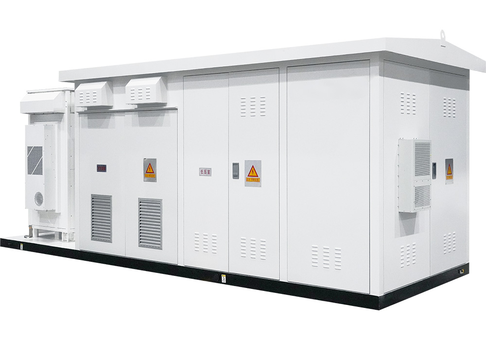
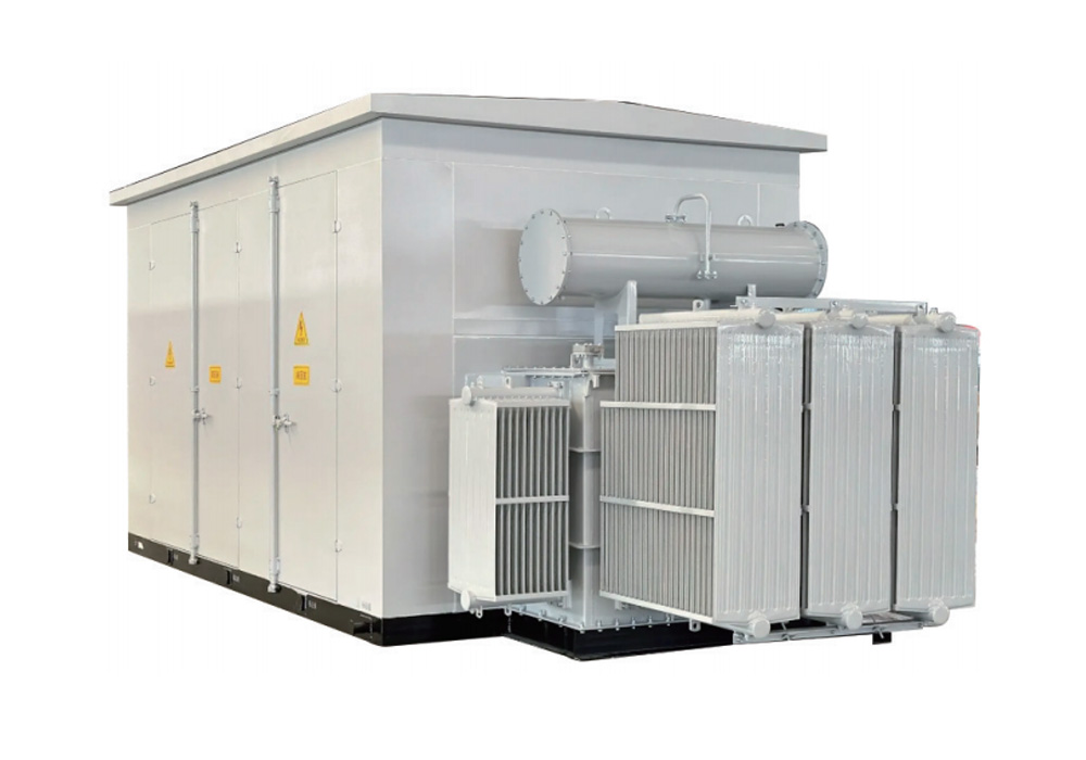
◆ Step-Up Transformer Cabin
The integrated cabin houses a transformer compatible with voltage levels up to 35kV for electrical energy steping up low-voltage output from the PCS to meet high-voltage transmission or load requirements. The system features comprehensive monitoring capabilities, supporting both local and remote integration.
◆ Integrated System
The cabin is equipped with an emergency lighting system, fire suppression system, access control, and cooling mechanisms. Fireproof partitions within the enclosure effectively ensure the safe and reliable operation of the integrated step-up cabin.
◆ Optimized Footprint & Design
The integrated design significantly reduces the footprint required for installation. Compared to traditional decentralized setups, it consolidates complex circuits and components within a single cabin. This minimizes interconnection cabling and line losses while creating a compact, cohesive system that allows for streamlined layout optimization in space-constrained environments.
◆ Peak Shaving and Load Leveling
The system enables energy storage and release in response to grid load fluctuations to achieve effective peak shaving. During peak demand, the energy storage system discharges to alleviate grid pressure; during off-peak periods, it absorbs surplus electricity. This prevents system overloads and maintains overall grid stability.
◆ Grid Stability Enhancement
The system improves grid frequency and voltage stability. In the event of significant fluctuations, the energy storage device can promptly discharge or store energy to maintain grid operation within reasonable parameters.
◆ Emergency Backup Power Supply
In the event of sudden grid failures or outages, the energy storage system can instantly switch to backup mode. It provides a continuous, stable power supply to critical loads, ensuring the uninterrupted operation of essential facilities.
Product Photos
Technical Parameters
| Parameters | 850V | 1500V | |||||||
|---|---|---|---|---|---|---|---|---|---|
| DC Side Parameters | Maximum DC Bus Voltage | 850V | 1500V | ||||||
| Maximum DC Side Current | 1147A*2 | 1147A*4 | 1935A*2 | 1935A*2 | 2500A*2/1935A*4 | 1935A*4 | |||
| DC Voltage Operating Range | 580V~850V | 1000V~1500V | |||||||
| Number of DC Input Circuits | 2 | 4 | 1/2 | 2 | 2 | 2 | 2/4 | 4 | |
| AC Side Parameters | Rated Power | 1000kW | 2500kW | 2500kW | 3150kW | 3450kW | 5000kW | 6250kW | |
| Branch Power * Quantity | 500kW*2 | 630kW*4 | 2500kW*1 1250kW*2 | 3150kW*1 | 1725kW*2 | 2500kW*2 1250kW*4 | 1563kW*4 | ||
| Maximum Output Power | 1100kW | 2750kW | 2750kW | 3465kW | 3795kW | 5500kW | 6250kW | ||
| Isolation Method | Transformer Isolation | ||||||||
| Reactive Power Range | 0~1050kvar | 0~2625kvar | 0~2625kvar | 0~3308kvar | 0~3623kvar | 0~5250kvar | 0~6250kvar | ||
| Rated Grid Voltage | 6kV/10kV/35kV | ||||||||
| Grid‑connected Operation Parameters | Rated Grid Frequency | 50Hz/60Hz | |||||||
| Total Current Harmonic Distortion Rate | < 3% | ||||||||
| Power Factor | -1~1 | ||||||||
| Rated Capacity | 1000KVA | 2500KVA | 2500KVA | 3150KVA | 3450KVA | 5000KVA | 6250KVA | ||
| Transformer Parameters | Transformer Type | Dry‑type/Oil‑immersed Transformer | |||||||
| LV/MV Voltage | 0.4/ (6‑35) kV | 0.69/ (6‑35) kV | |||||||
| No‑load Loss | Compliant with National Standards | ||||||||
| Load Loss | Compliant with National Standards | ||||||||
| No‑load Current | Compliant with National Standards | ||||||||
| Impedance | Compliant with National Standards | ||||||||
| System Parameters | Permitted Ambient Temperature | -30℃ to +60℃ (Derating above 40℃) | -30℃ to +60℃ (Derating above 45℃) | -30℃ to +60℃ (Derating above 50℃) | |||||
| Permitted Relative Humidity | 0~100% | ||||||||
| Permitted Altitude | <5000m (Derating above 2000m) | <5000m (Derating above 3000m) | <5000m (Derating above 4000m) | ||||||
| Protection Rating | IP54 | ||||||||
| BMS Communication Interface | RS485 | ||||||||
| EMS Communication Interface | Ethernet | ||||||||
| Communication Protocol | Modbus RTU/Modbus TCP/IEC104/IEC61850 | ||||||||
| Compliance with Standards | GB/T34120,GB/T34133,GB/T36547 | ||||||||
| Grid Support | High/Low Voltage Ride‑Through (HVRT/LVRT), Frequency Regulation, Voltage Regulation, Grid‑Forming Function, etc. | ||||||||
| Overall Dimensions | Depending on Specific Configuration | ||||||||
| Weight | Depending on Specific Configuration | ||||||||
Send Inquiry
Room 1102, Block A, Building 6, Expo Bay Zhonggang Plaza, No. 83 Zhanjing Rd, Bao’an District, Shenzhen, China 518103
+86 180 9898 3521
sales@euepower.com
Mon - Fri: 8:30 - 17:30 BJT
 English
 Русский